
Last year (2020) in June, I purchased an ICOM IC-9700 VHF\UHF radio after working at a big box home improvement store for a few months. Initially it wasn’t supposed to arrive until mid July but then I got notice that it would arrive before ARRL Field Day
I hurriedly tried to build a 2 meter and 70 cm antenna system for satellite communications to make contacts during the ARRL Field Day event. I choose to build a pair of crossed Moxon antennas as described by L. B. Cebik, W4RNL(SK), in the article A Simple Fixed Antenna for VHF/UHF Satellite Work in the August 2001 QST. There is a follow up article Regarding “A Simple Fixed Antenna for VHF/UHF Satellite Work” (Technical Correspondence) in the October 2001 QST. Note that the links are to the ARRL QST Archives and you must be an ARRL member to access them; however, I have found the articles elsewhere on the Internet. I had already chosen to build these antennas before I got my new radio as the antenna system offered approximately the same performance as turnstile antennas but without the large ground planes involved. I also believe that they offer the same performance as “Eggbeater” antennas.
My 2 meter antenna was made from 1/4 inch aluminum rod from the hardware store. I thread the connection ends of the driven elements with 1/4-20 threads and used 1/4-20 hardware to install them. The 70 cm antenna was made from 12 gauge solid copper wire. I tried to use 3/32 aluminum welding rod but to my dismay and misunderstanding, you cannot thread the welding rod with 2-56 threads; you need 3-56 threads on the aluminum rod. I have to give a hat-tip to The Silicon Graybeard for pointing this out and informing me that the 12 gauge wire would work with a 2-56 thread. Threading the copper wire is a departure from the design in the article but with work hardening of the copper, it works.
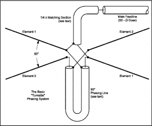
In my hurry to build them, I first misinterpreted the impedance transformer section. A single Moxon antenna presents a 50 ohm impedance . When crossed per the article with a 1/4 wave phasing line, the feed point impedance of the array is 25 ohms (two antennas in parallel). You need to transform this up to 50 ohms for the normally used types of coax. Not carefully reading the article, I first thought that you used a single 1/4 wave section of 75 ohm coax to effect this transformation based on the following diagram:
Boy was I wrong! I had built both the 2 meter and 70 cm antennas with phasing sections and impedance transformers, the connecting coaxes, and gotten them up on a PVC pipe mount. When I applied power the SWRs were UGLY to say the least.
So I went back and reread the article to find out that I should have built the impedance transformers out of parallel sections of 75 ohm cable to create a 37.5 ohm transmission line transformer. So I went back and rebuilt the impedance transformers and installed them. I also got smart and pulled out my nanoVNA (Vector Network Analyzer) to check the fitness of the antennas with the new impedance transformers. Woops! The SWR was still UGLY but not quite as bad. However, there were weird things going on. I posted about this in this thread in the Technical Forums on QRZ.com, Cebik’s crossed Moxon antennas for satellite . That thread has more detail about what I was going through and did in that time period plus some pictures of my antennas. But to sum it all up, I still was not where I wanted to be or needed to be.
I did contact a fellow amateur operator who is truly an antenna expert. He worked for a nationally known development facility doing amongst other things antenna design and currently teaches some folks in the military about antennas. He suggested a different approach to the coax harnesses which I am going to employ on the 2 meter antenna.
For the 70 cm antenna, I am going to use a slightly different design by L. B. Cebik.
I will be back with further adventures in this current antenna project in another installment as I think I have rambled enough here.
What are you planning on using for a preamp? If you plan on working any of the linear (NON-FM) satellites you’ll need a preamp, as the signals are much weaker.
drjim, I saw your other comment in email but missed this one.
I don’t have an antenna mounted pre-amp to use. However, a couple of years ago on ARRL Field Day, I was using my IC-821H with only its internal pre-amp and heard the linear satellites. The antennas were verticals that were made primarily for FM and set about 20 feet above the ground. When one satellite made a near overhead pass, I was unable to hear it during the highest portion of the pass.
Using that information I was just going to go barefoot with my IC-9700 and its internal pre-amp. I have read folks on QRZ.com making the same comment about the need for a pre-amp on linear birds. If I had the bucks I would get a Yaesu Az-El rotator and use crossed Yagi antennas for all modes. But alas, that is not currently in the books.
Good luck with that. Antennas seem to biting a lot of folks in the butts lately!
Who’s been having antenna problems, Old_NFO? One of the Ham antennas recently deployed on the ISS has some issues requiring another EVA, but that’s all I’ve heard about…